
Symbol |
Name |
Description |
 |
Relay Contact | Shown with relay in de-energized or in reset position. (Show relay coil designation near contact.) |
 |
Timing Relay Contact | TDC indicates contact closes at end of timing period. TDO contact opens at end of timing period. |
 |
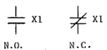
Coil |
Relay, contactors, circuit breaker, solenoid etc. (Show device designation, X1) |
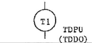 |
Coil | Timing Relay – TDPU indicates timing period starts when coil is energized. TDDO indicates timing period starts when coil is de-energized. |
 |
Latching Relay or Mechanically Contractor | O=Operate; R=reset; TC=trip coil; CC=closing coil. (Coils may be seperated on diagram) |
 |
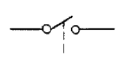
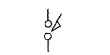
Knife Switch | If shown closed, terminals must be added. |
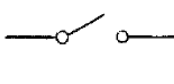 |
Switch – General | Single pole, single throw. |
 |
Switch | One pole of multi-pole switch shown. Other poles shown elsewhere. |
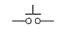 |
Pushbutton | Momentary or spring return. Single Circuit(make) |
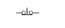 |
Pushbutton | Momentary or spring return. Single Circuit(break) |
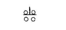 |
Pushbutton | Momentary or spring return. Two Circuit. |
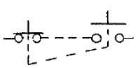 |
Pushbutton | Maintained, two circuit. |
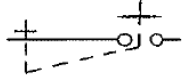 |
Pushbutton | Maintained, single circuit. |
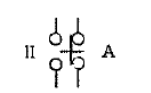 |
Selector Switch | Two position, maintained designate position shown; ie. A=Auto; |
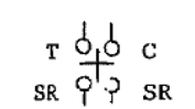 |
Selector Switch |
Three position, SR indicates spring return from position so labeled. “TRIP-NORMAL-CLOSE position shown. |
 |
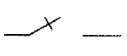
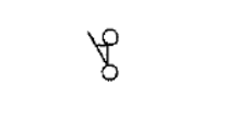
Limit Switch | Normally open – not applicable for Motor Operated Valves and Solenoid Valves. |
 |
Limit Switch | Normall closed – not applicable for Motor Operated Valves and Solenoid Valves. |
 |
Used with other symbols to indicate device is adjustable | |
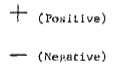 |
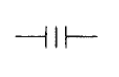
Polarity Markings | Direct current. |
 |
Instantaneous Polarity Markings | |
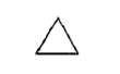 |
3-phase, 3-wire, delta | |
 |
3-phase, 3-wire, open delta grounded | |
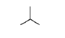 |
3-phase, 3-wire, wye | |
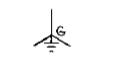 |
3-phase, 3-wire, wye grounded neutral | |
 |
3-phase, 3-wire, zigzag | |
 |
3-phase, 3 wire zigzag, grounded neutral | |
 |
Connection to earth ground | may be plant grounding system |
 |
Connection to chassis or frame | |
 |
Terminal | may be added to any of the following symbols at connection points. |
 |
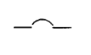
Short circuits | (not a fault) |
 |
Terminal | designates termination of field run cables to main control board, main control board termination cabinet or emergency power board termination cabinet. |
 |
Flow Switch | Closes on increase in flow at value shown. |
 |
Flow Switch | Opens on increase in flow at value shown. |
 |
Flow Switch | Closes on decrease in fow at value shown. |
 |
Flow Switch | Opens on decrease in flow at value shown. |
 |
Liquid Level Switch | Opens on rising level (Closes on low level) |
 |
Liquid Level Switch | Closes on rising level (Opens on low level) |
 |
Pressure or Vacum Switch | Closes on rising pressure switch. |
 |
Pressure or Vacum Switch | Opens on rising pressure (Closes on increase in vacuum) |
 |
Temprature Switch | Closes on increasing tmp. |
 |
Torque Switch | Opens on high torque. |
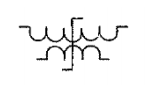 |
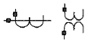
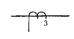
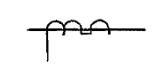
Transductor | Control winding shown with 5 loops. Power winding shown with 3 loops. |
 |
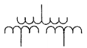
Transformer | General, two winding |
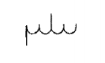 |
Autotransformer | General |
 |
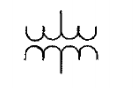
Transformer | General, three winding |
 |
Current Transformer | number represents quantity |
 |
Bushing Type Current Transformator | |
 |
Potential Transformer | Number represents quantity |
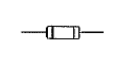 |
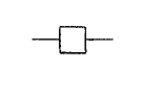
Fuse | General |
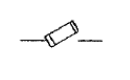 |
High Voltage Primary Fuse Cutout | |
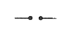 |
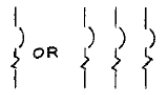
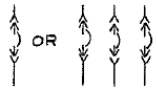
Lighting Arrester | General Gap Type |
 |
Lighting Arrester | Valve or film type |
 |
Circuit Breaker | General |
 |
Power Circuit Breaker | Show location of operating mechanism |
 |
Circuit Breaker | 3-pole with magnetic – overload device in each pole. |
 |
Circuit Breaker | 3-pole, drawout type (Used in metal clad switchgear groups) |